Hydraulic Cylinder Force
This force element applies a force vector acting from the reaction body onto the action body. The force amplitude is computed such, that the behaviour mimics a hydraulic cylinder. The force direction points from the Reaction Mate Connector to the Action Mate Connector. The hydraulic cylinder aims to prescribe a piston motion starting at the current postion at and ending after the Motion Duration at the desired Piston Travel. To show a saturating behavior when a certain Maximum Force is exceeded, you can also specify a meaningful value for it.
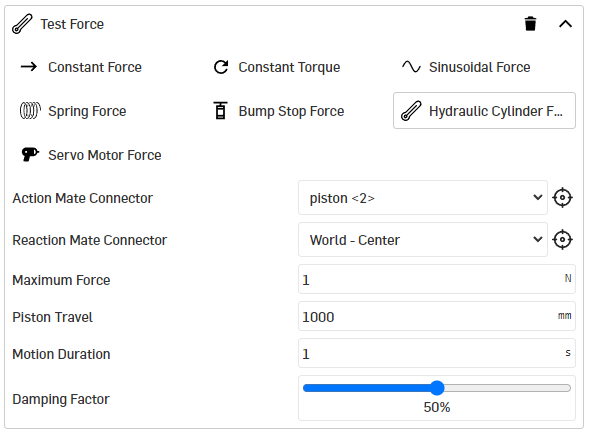
Action Mate Connector
Specify a mate connector to define the body and exact point on which the force is applied.
Reaction Mate Connector
Specify a mate connector to define the body and exact point on which the reaction force is applied.
Maximum Force
Defines the force limit of the hydraulic cylinder. This may correlate with the oil pressure limited by a pressure relief valve (multiplied with the piston area). Provide a value in the unit you selected for Force.
Piston Travel
The desired piston travel. Provide a value in the unit you selected for Length.
Motion Duration
The duration specifies the function used as the desired trajectory from the start of the motion to the stationary end position. The time unit is set to seconds.
Damping Factor
A relative damping factor relates the damping force with the force necessary to drag along the desired trajectory (damping relative to the first time derivative of the desired trajectory), where is no damping and is maximum damping.
principia MBS auto-generates a smooth trajectory from current to desired piston position. A ninth order polynomial is used to avoid unphysical accelerations.
Test this element starting with zero damping!
After a successful test, you can then increase the value for the damping so that the desired behavior is achieved.